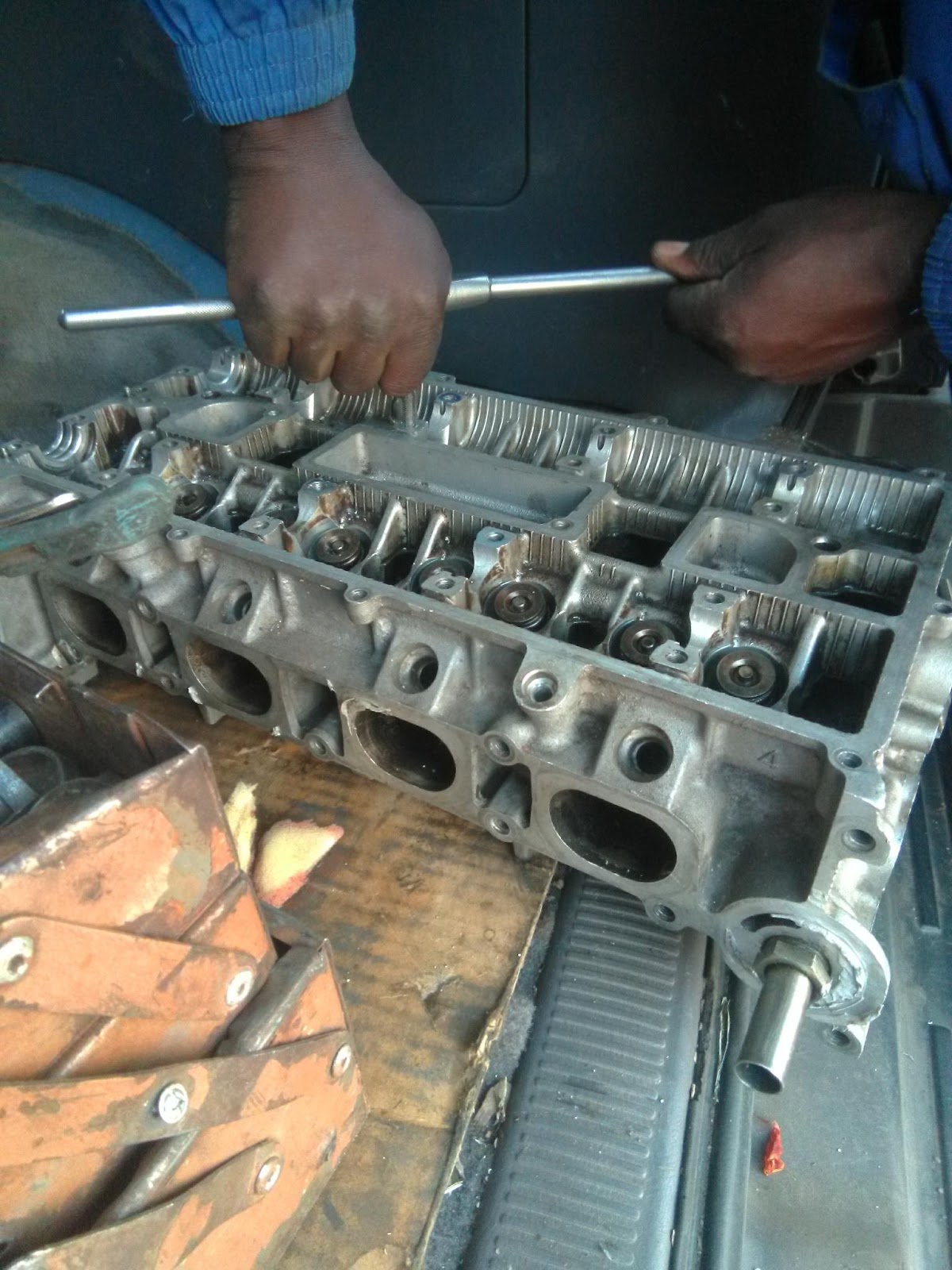
A few of the threads that hold the camshaft caps were damaged so I am running a tap so that I can fit helicoils.
Wednesday, November 7, 2018
Tuesday, January 3, 2017
Rain gauge
This is how I can tell the level of rain that we have received. No need for fancy gauges. The only snag is I have to empty it before I can use it.
Monday, September 12, 2016
Ignition switch
I recently had the task of fitting an ignition key for a Nissan Champ 1400. I thought this was a walk over. Given that I have just done a suspension overhaul as we as an engine service with no sweat.
Alas. It was not to be. The terminals on new ignition key were completely different from the old key. I reluctantly gave that job to an auto electrician and made a note to brush up on my auto electrics.
Sunday, February 2, 2014
Wednesday, January 30, 2013
Saturday, May 17, 2008
Cylinder Head Straightness
Remove any gaskets or carbon on the fat face that seats against the block.
Place a Straight edge firmly on the cylinder head face and see if there is gap between the straight edge and the cylinder head. If there is a gap measure with a filler gauge to determine if the warpage is within tolerance or it requires skimming. With experience you won’t even need a filler gauge to make this judgement.
This skill helps at the counter to inform the customer and make further diagnosis.
Wednesday, March 26, 2008
CYLINDER HEADS: Receiving the job.
In this first part of my ‘cylinder head’ series I am going to talk about how best to receive a job to recondition a cylinder head. I found these checks very useful because I could quickly give feedback to the customer while he was still at the counter. I could advise them on thinks like: possible spares to buy, how I was going to approach the job, how long the job might take and warn them of any potential dangers (It makes good business sense to ask customers to sign a disclaimer when the risks are high or when the customer insists on a modification against your better judgment).
Customers, particularly those with a technical know-how, appreciate it when you take time to explain the logical steps that you are going to take to tackle the job. More often than not it is the mechanic who brings in the job rather than the accountant. This is one of those things that builds trust. If their job is done well, next time they come in they won’t really want to know how you are going to do it, they just want you to do it because you will have gained their confidence.
Some customers prefer to source their own spares. When it comes to commercial transporters they want there vehicles ready yesterday because downtime is costly.
So if you can predetermine some of the spares that they need to get it will save a lot of time. For instance if the cylinder head has overheated they obviously need to get a new set of valve stem oil seals for you to fit.
In the following articles I would like to highlight some signs that can help you give a general diagnosis and prognosis. Like any good doctor do not forget to verify these findings with clinical tests before administering the cure on the head cylinder –I mean cylinder head.
Saturday, February 23, 2008
Unisa

Monday, February 11, 2008
Valve Seat Material
Now this got me thinking: what is the fate of all those cylinder heads that we fitted with cast iron exhaust seats? How significant is this wear?
Friday, January 18, 2008
Small end recondition
Sequence of operation
- Tidy workstation, observe safety precautions and check accuracy of measuring instruments.
- Srip and clean connect rod assembly
- Chech that the oil galleries are clear.
- Assemble and touque to the crrect load using a torque wrench.
- Align connecting rod in alignment fixture.
- Using a suitable jig press out small end bush on a press and remove any burrs in the rod eye.
- Drill oil holes before or after pressing in the new bush with a jig, as is suitable.
- Setup connecting rod on the connecting rod standardising machine with truing cones and then clock small end bore true to the spindle axis with a dail test indicator mounted on the boring bar.
- Measure bore with T-guage and outside micrometer and determine size to be bored to.
- Grind and lap tool to the correct angle and radius.
- Secure tool in boring bar at the correct height using a direct reading micrometer.
- Bore to size.
- Remove connecting rod from machine and clean.
Be a better friend, newshound, and know-it-all with Yahoo! Mobile. Try it now.
Crankshaft Grinding
Sequence of operation
- Tidy workstation, observe safety precautions and check accuracy of measuring instruments.
- Check the thrust collars with a t-gauge and outside micrometer.
- Check journal size with an outside micrometer.
- Determine size to be ground to and availability of bearings.
- Check for bow and twist with a dial test indicator (DTI) on a magnetic base and the crankshaft on 'V' blocks.
- Crack test with a magnaflux machine.
- Stress relieve for two hours at 150 degrees Celsius. Most, including me, believe this step is not necessary.
- Mount a balanced grinding wheel on the crankshaft grinding machine. True the wheel and dress it to the correct corner radius.
- Lock the machine Chucks in position 'A'.
- Set cross slides and outboard counterweights to zero.
- Secure the crankshaft in the chucks and make sure it rotates in the same direction as it would in the engine. The crank nose normally goes into the left chuck.
- Set the front and rear journals true with a DTI.
- Set the continuous measuring gauge.
- Turn the machine on and plunge grind a journal leaving 0.03mm from finish size (Do this with a continuous supply of coolant).
- Traverse grind the journal to finish size.
- Repeat for other main journals.
- when the main journals are complete Lock the chucks in position 'A'.
- Set a plane of big-ends journals parallel to the bed using a munk.
- Move cross slide simultaneously to give the correct throw on vernier slides.
- Set outboard counterweights to balance the crankshaft.
- Complete setting the big-end journal plane using a DTI and a stoke indicator gauge.
- Balance the shaft again using counterweights.
- Set continues measuring gauge.
- Grind to size as with mains.
- Repeat for other journals in the same plane.
- Rotate index plane to the next plane.
- Set plane as with previous journals and grind accordingly.
- Repeat grinding procedure for all planes. The common four cylinder inline shaft normally has two big-end planes only.
- Dry the journal with a cloth and polish with a super-finnisher tape.
- Oil shaft and remove from the machine.
- Dynamic balance the crankshaft.
Tuesday, January 15, 2008
Cyliner head Recondition (Overview)
Any reputable shop will Magnaflux or pressure check the castings for cracks and measure the combustion chamber volume to determine if and how much the head surface has been cut.After inspection, the cylinder head-to-block surface should be resurfaced the minimum amount to ensure a flat sealing surface ( Please refer to previous article on cylinder head surfacing). Next hardened valve seats to combat erosion from the effects of unleaded gas should be installed. This is a fairly expensive operation but essential if you plan on getting 50,000-100,000 miles out of your rebuild. Next the valve guides and valves should be inspected for wear and replaced if necessary. A precision valve job to factory specs is next. Then the heads should be assembled with new valve stem seals with valve springs shimmed to the correct seat pressure.
Be a better friend, newshound, and know-it-all with Yahoo! Mobile. Try it now.
Saturday, December 29, 2007
HAPPY NEW YEAR
i had taken a bit me a break but watch this space for plenty me informative blogs in 2008.
CHEERS!
Wednesday, September 26, 2007
Skimming Cast Iron Cylinder Heads
Monday, September 24, 2007
Cylinder Block Rebore

Wednesday, September 19, 2007
My Mission
Seriously! This is what I intend to do. This is the first of series of articles where I will be talking mainly about automotive precision machining. I will try to share with you from my 9 years experience (4yrs appy & 5 yrs post appy).
I am hoping that this will be a launch pad to establish some concise forum for the machining aspect of automotive engineering.
One thing that has always been eating me is that, to the best of my knowledge, there are no specific books for Automotive Precision Machining. During my years of training we tied General Machine Shop Technology books with Motor Vehicle Technology books to get a theoretical understanding. The gaps where filled in by notes from the lecturer and plenty research.
I plan on coming up with one book that covers all these basics in this specialised field.
I will probably also drag you through a few sequences of operation in the hope of teaching you what I know but mainly so that I may learn from you through your comments.
Tuesday, September 18, 2007
WELCOME.
This is the first of a series of posting where i will be talking mainly about the machining aspect of automotive engineering. I trust that you will enjoy exploring the exciting world of precision engineering as much as i enjoy writing the articles.

